Panel and fixing layout
You provide the location, height, design pressure and substrate. We prepare a preliminary panel size, frame, fixing-density and rail-spacing proposal for the project engineer to review.
6 mm sintered stone facade panels and dry-hang systems
Send us the project location, building height, elevations, substrate and target finish. We review the panel module and fixing direction, prepare samples and drawings, then supply cut, backed, drilled and numbered panels with matching dry-hang components.
Problems we resolve before production
The order must connect panel size, design wind pressure, substrate, rails, brackets, joints, fabrication drawings, panel numbers, packing sequence and the documents required by the project team.
This can create late drawing changes, extra site cutting, unclear component responsibility and crates that do not follow the installation order.
Our team reviews the drawings, confirms the panel schedule and system scope, prepares a sample or mock-up, and fabricates labeled modules against the approved information.
You provide the location, height, design pressure and substrate. We prepare a preliminary panel size, frame, fixing-density and rail-spacing proposal for the project engineer to review.
You provide elevations and typical sections. We coordinate panel joints, window returns, corners, soffits and representative fixing nodes before cutting starts.
After drawing confirmation, we cut, drill, apply the specified backing or frame, assemble components, inspect dimensions, label panels and map the crates to the elevation sequence.
You tell us the target market and specification. We compile the available material reports, system information, production checks and packing records required for technical review.
System anatomy
A large-format architectural surface selected for exterior exposure, lower panel weight and the required facade finish.
The facing is integrated with a project-configured aluminum support assembly to improve panel stability, handling and modular installation.
An aluminum cone-core backing option distributes forces across the panel and helps retain fragments if the facing is damaged.
Concealed mechanical connections transfer loads into the frame while allowing individual modules to be installed, adjusted and replaced.
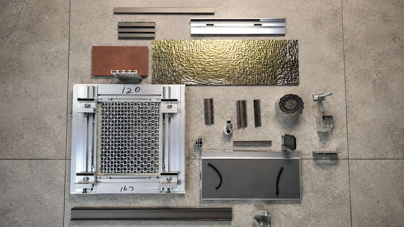
Primary and secondary rails, brackets, stainless fasteners and anti-loosening components support alignment on concrete or steel substrates.
The project wall build-up can coordinate insulation, water-resistive layers, ventilation, drainage and required fire-stopping.
Choose the supply boundary
For facade contractors that have their own approved fabrication and assembly capability.
For buyers who want more work completed before material reaches the construction site.
| Your project input | What Funtek prepares | Procurement risk reduced |
|---|---|---|
| Location, height and design wind pressure | Preliminary panel, fixing and rail-spacing review | An under-defined or unsuitable system basis |
| Elevations, sections and typical nodes | Panel layout, joints, cut list, numbering and detail coordination | Field improvisation, excessive waste and mismatched modules |
| Substrate and proposed wall build-up | Substructure interface, cavity and access coordination | Conflicts with anchors, insulation, drainage and fire-stopping |
| Finish, area and project schedule | Samples, batch plan, fabrication sequence and packing map | Approval delays, color inconsistency and delivery confusion |
| Target market and approval requirements | Available material and system documentation package | Late-stage evidence gaps during technical review |
System components
A 3.0 mm aluminum frame is available within the referenced system configuration. Final section and thickness are confirmed against panel format and project loads.
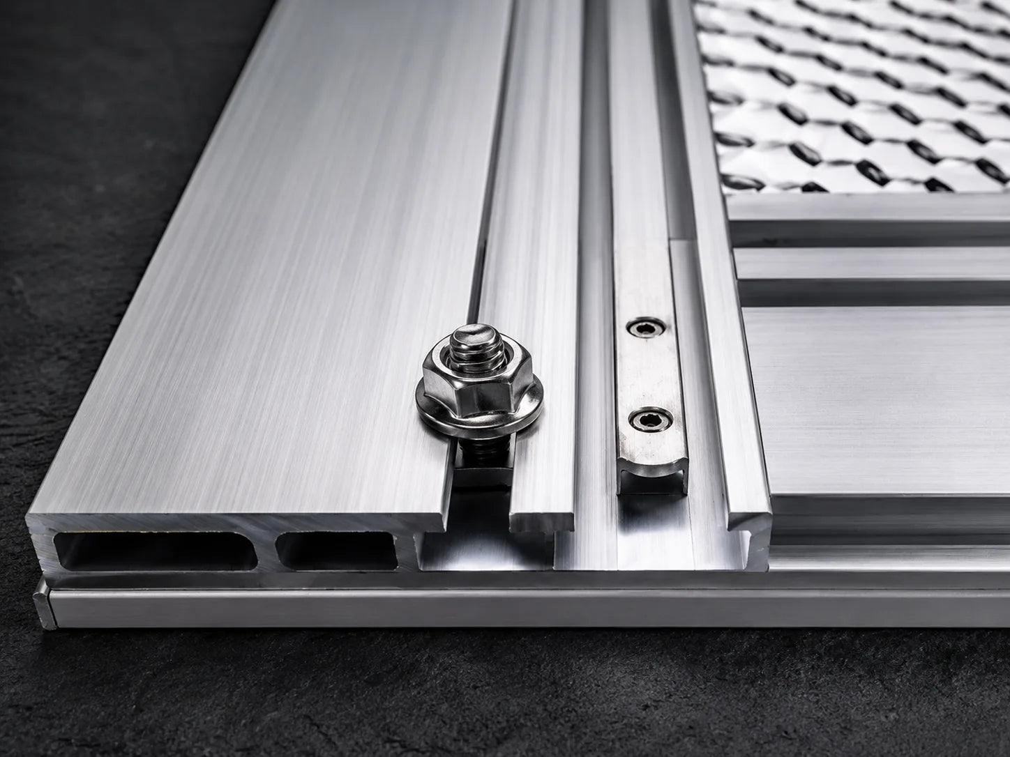
Visible nuts and bolts use stainless material with anti-loosening details to support durable mechanical connections.
Concealed connectors keep frame joints clean and distribute force without relying on exposed weld points.
Individual modules can be accessed and replaced without dismantling the entire elevation, subject to the final joint and fixing design.
Actual system demonstration
Technical review package
The document list is confirmed before quotation. We provide available reports for the selected material and agreed system scope; the project designer determines whether additional full-wall or jurisdiction-specific testing is required.
From drawings to delivery
From appearance to installation
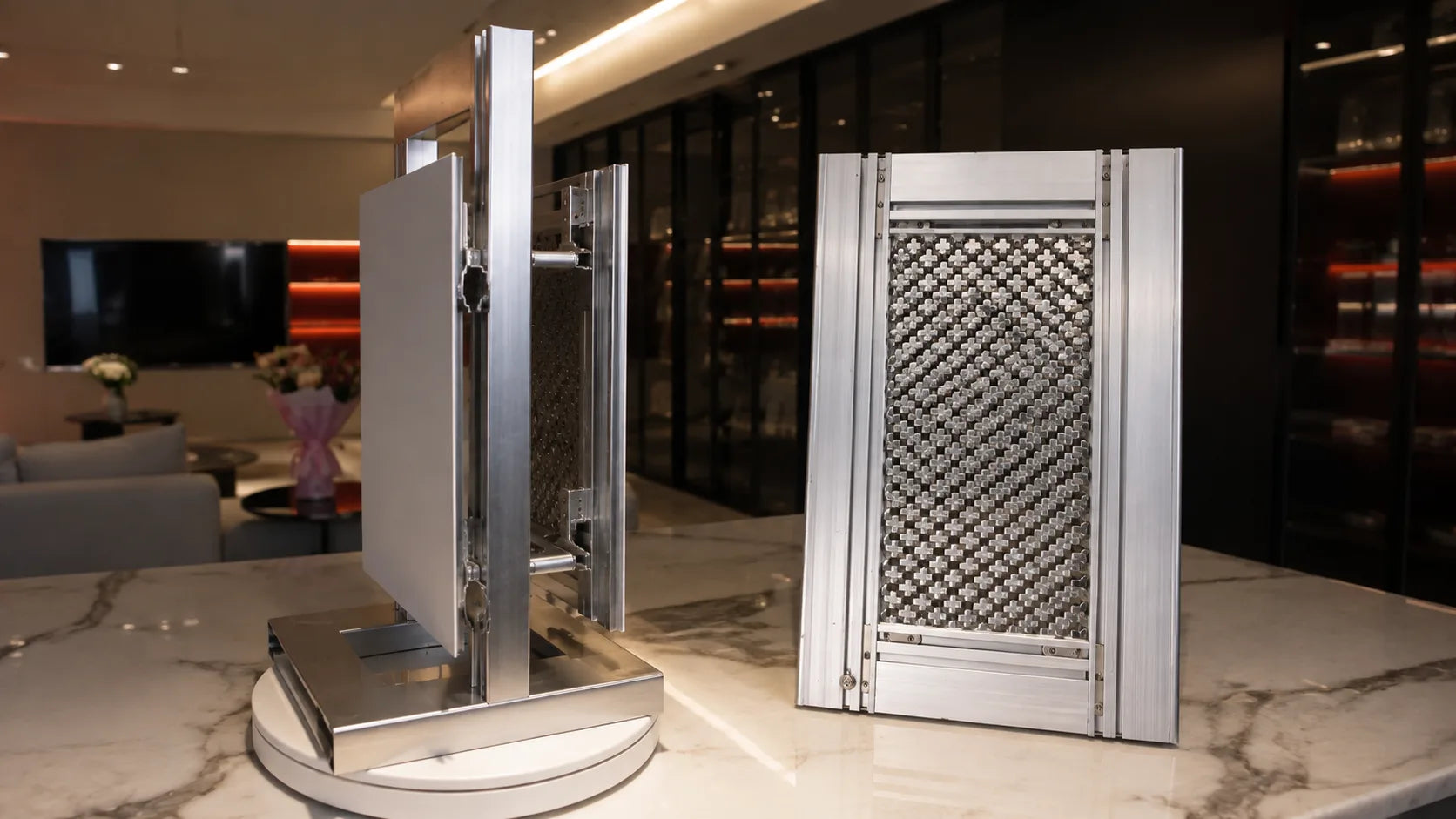
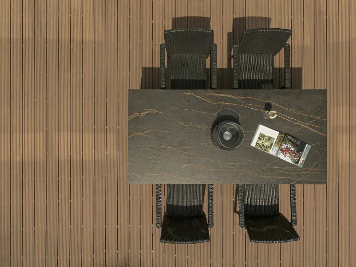
The system photographs are from the supplied physical mock-up. The building and installation views illustrate the intended application and will be replaced with your completed-project photographs when available.

Use this view to discuss panel scale, joint rhythm, corners, window returns and finish selection.

The mock-up shows the profiles, adjustable connections, fasteners and access behind the facing.

Rails are aligned first; prepared modules are then positioned, adjusted and checked against the approved joint layout.
Buyer questions
Project review
We use these inputs to confirm the material, supply scope, fabrication route and quotation basis.