Adhered cladding
Panels are bonded to a prepared substrate with an installation system selected for the panel, wall condition, height and local requirements.
Confirm substrate, adhesive, panel format, joints and installation height.
Facade systems / technical project supply
Planning a sintered stone exterior but unsure how the panels should be fixed? Send the elevation, building location, substrate and approximate facade area. We help organize the material, panel layout, compatible fixing direction, packing sequence and the questions your local facade engineer must confirm.
Installation language / 01
International project teams usually describe the wall by how it is fixed and how the cavity manages water, air and insulation. Use the terms below to begin the right conversation without assuming that every mechanically fixed wall is automatically a rainscreen.
Panels are bonded to a prepared substrate with an installation system selected for the panel, wall condition, height and local requirements.
Confirm substrate, adhesive, panel format, joints and installation height.Panels or backed panel assemblies connect to rails and brackets through concealed or visible mechanical components.
Confirm loads, anchors, panel module, rail spacing, tolerances and access.The mechanically supported outer skin is coordinated with a drained or ventilated cavity, weather barrier, insulation and project-specific fire and closure details.
The complete wall assembly must be designed and approved for its climate and jurisdiction.When to investigate mechanical fixing / 02
Mechanical fixing is not automatically the best answer for every wall. Height, substrate, wind and seismic design, panel geometry, cavity requirements, fire strategy and replacement access must be reviewed together.
Building height, location, wind exposure and seismic conditions influence panel size, support spacing and anchoring.
A required drainage plane, insulation layer or ventilated cavity changes bracket depth, closures and interfaces.
Windows, returns, soffits, parapets and corners must be coordinated before the panel schedule is treated as final.
If individual replacement matters, the fixing sequence, joint access and spare-panel plan should be discussed early.
Two project routes / from the source system
The source system separates commercial and public facades from villas and low-rise buildings. Both can use mechanically fixed, factory-prepared panels, but their load path, cavity, fire, waterproofing, access and approval requirements are not interchangeable.
01 / Commercial and public buildings
For offices, hotels, hospitals, schools and industrial parks, the panel package must sit inside a project-specific facade design.
02 / Villas and low-rise buildings
Low-rise work may use a lighter subframe and concealed hangers, but windows, corners, recesses, parapets and the wall base remain technical details rather than decorative afterthoughts.
Factory preparation cannot compensate for missing site dimensions. Both routes require verified substrate information, coordinated drawings, an approved material and system mock-up, clear panel references and a packing plan that matches the receiving sequence.
Assembly anatomy / 03
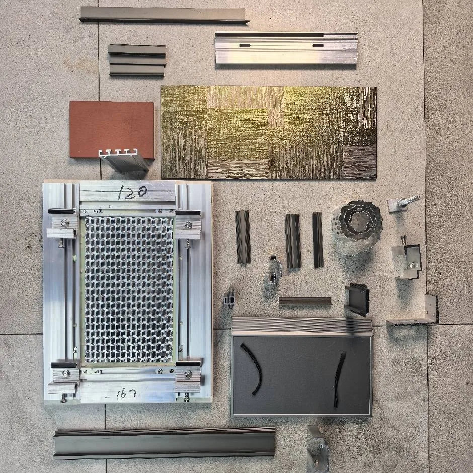
The supplied reference system combines a sintered stone face with a 3.0 mm aluminum perimeter frame, an aluminum cone-core backing panel, concealed connectors, stainless-steel fasteners and modular hanging components. Rails, brackets, anchors and envelope layers are then coordinated to the actual building.
The physical kit shown is a system reference, not a universal construction detail. Final panel size, backing, fasteners, spacing, corrosion class, cavity barriers, waterproofing and structural connections must be specified and approved for the project.
Physical system references / 04
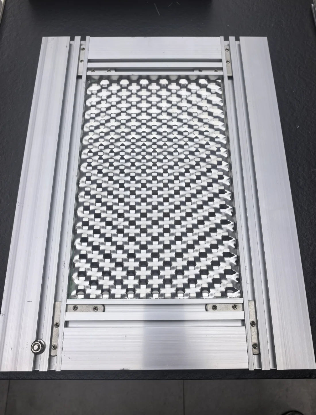
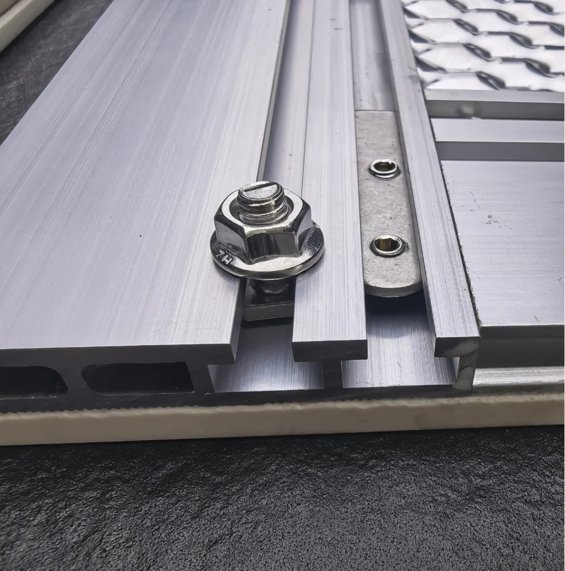
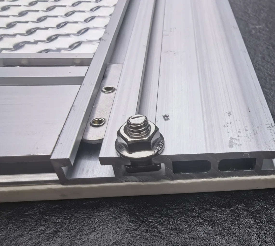
The original presentation identifies four configuration decisions that should be checked before quotation: what is included in the kit, how the 3.0 mm frame supports the cone-core backing, how visible fasteners are locked, and how concealed connections permit alignment and planned replacement.

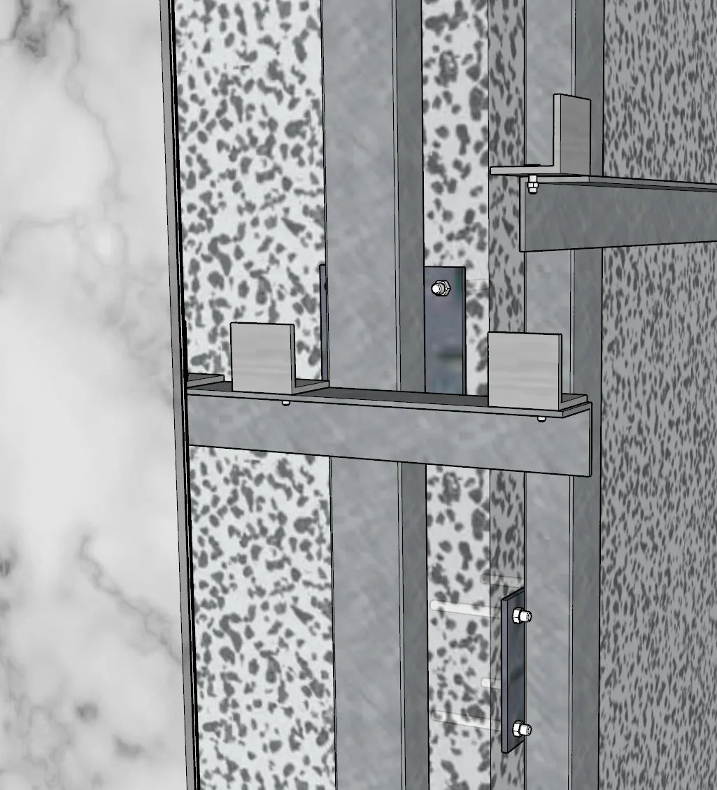
Review the backed module, perimeter profiles, rails, hangers, connectors, fasteners and closures together. Confirm which components are included in the quotation and which belong to the local facade package.

The source module uses a thicker aluminum perimeter frame and cone-core backing to support a large-format panel, manage flatness and spread connection forces through the prepared assembly.

Visible nuts and bolts in the reference kit are stainless steel and paired with locking washers. Grade, quantity, tightening procedure and inspection remain project-specific.

Internal frame connectors keep the perimeter visually clean and distribute force without relying on exposed welded joints. Replacement access must be designed into the hanging sequence before installation.
Junction register / 05
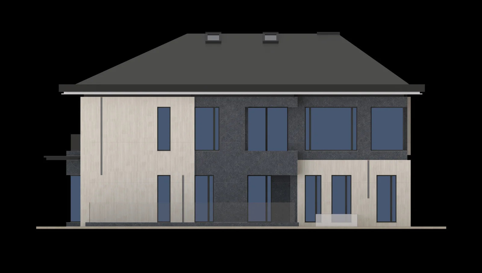
The source project includes full elevations plus rail, corner, sloped-wall, window-sill and recessed-joint studies. That is the right sequence: resolve the building interfaces before treating the facade as a square-metre material order.

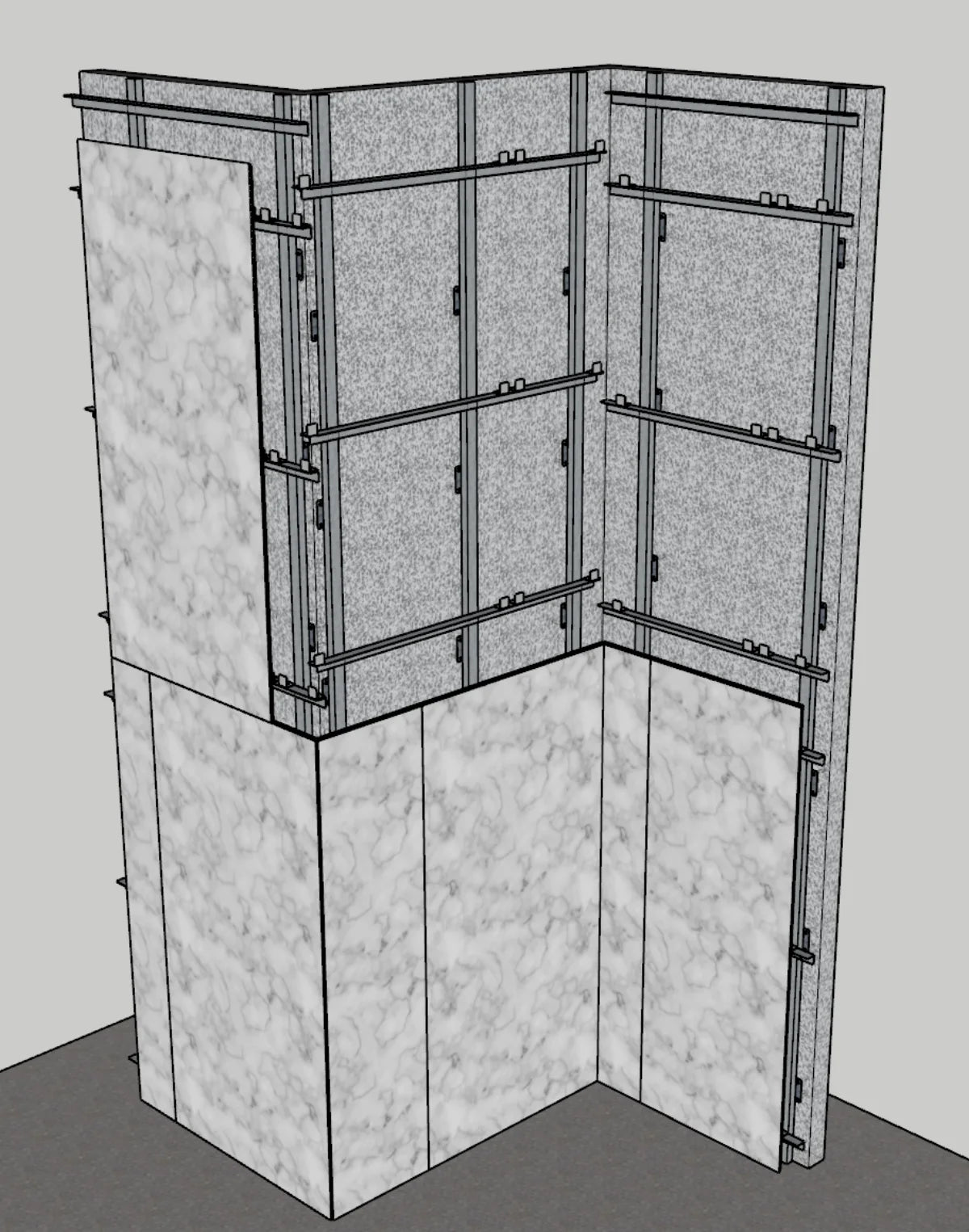
The project model shows primary rails, secondary rails, brackets and anchors as a connected load path. Actual member sizes, fixing centres and substrate anchors must come from the approved engineering.

The corner model makes panel returns, rail direction, installation access and the order of adjacent panels visible before finished sizes are released.
Confirm the finished module, joint rhythm, rail direction and adjustment range before the panel schedule is frozen.
Mark: panel grid, structural datum, movement zones and acceptable joints.Decide whether the surface turns, returns, mitres or terminates at a profile. The visual decision changes finished sizes and support positions.
Mark: corner type, return depth, vein direction and visible edge.Treat the opening as a coordinated set. Head drainage, jamb returns, sill slope and frame interfaces cannot be resolved from facade area alone.
Mark: frame position, reveal depth, sill condition and perimeter joint.A recessed band changes bracket depth, return panels, joint alignment and installation access. Show it in section as well as elevation.
Mark: depth, return finish, joint continuation and access sequence.Coordinate ground clearance, drainage, impact exposure, flashing and the first support line before setting the lowest panel module.
Mark: finished grade, drainage route, clearance and closure.Upper terminations must coordinate panel support with coping, water management, ventilation and movement at the roof edge.
Mark: coping, cavity closure, ventilation path and waterproofing interface.The reference models and diagrams explain coordination intent. They do not establish final dimensions, drainage, waterproofing, structural capacity or code compliance.

From elevation to crate / 06
A coordinated facade package connects the architectural elevation to panel references, inspection, packing and site identification. Confirm identification requirements before production rather than rebuilding the sequence after shipment.
Surface direction / 07
Exterior suitability, finish, thickness and exact availability must be confirmed for the selected product and project. Use these cards to begin a visual shortlist, not as an automatic facade specification.
Responsibility map / 08
Your dedicated Funtek contact helps organize the material and supply information. The responsible project team confirms the final wall design, calculations, approvals and installation.
Funtek project supply
Project design and site
Facade brief builder / 09
A reference image, marked PDF or rough elevation is enough to start. Tell us what has already been confirmed. Your dedicated Funtek contact will help organize the missing material and supply information.
Project path / 10
The sequence can be adjusted to the project, but drawings, mock-ups, approvals and identification should be resolved before the facade becomes a shipping problem.
The project team confirms dimensions, supporting-wall condition, datum levels, openings, access and the locations that require survey rather than estimation.
Coordinate panel modules, rails, brackets, anchors, cavity depth, corners, recesses, windows, parapets and base details with the responsible facade engineer.
Confirm the sintered stone design, finish, joint appearance, backed-panel build-up, visible hardware, tolerance and representative junction before production.
Cut and process the approved material, assemble the specified backing components, apply panel references and inspect against the agreed schedule.
The qualified site contractor installs and verifies anchors, brackets and rails, then establishes the adjustment range required for the prepared panels.
Panels are installed to the approved sequence; joints, corners, openings, drainage, waterproofing and cavity closures are checked as coordinated work.
Record panel and crate references, agreed inspection results and any spare-panel or replacement procedure needed for future maintenance.
Specification questions / FAQ
It is an exterior cladding approach in which a prepared sintered stone panel or panel assembly connects to rails, hangers, brackets or other engineered mechanical components instead of relying only on direct adhesion. The exact assembly must be selected and approved for the project.
Not automatically. Mechanical fixing describes how the panel is supported. A ventilated facade or rainscreen also depends on the designed cavity, drainage or ventilation path, weather barrier, insulation, closures and other building-envelope details.
Thickness cannot be selected from building type alone. Panel format, backing concept, fixing method, loads, finish, edge processing and the tested or engineered assembly all affect the decision. We can confirm current material options while the responsible engineer approves the final system.
Concealed attachment may be possible depending on the panel assembly, backing, rail system, joint access and engineering requirements. Send the target appearance and junction details so visibility and replacement access can be reviewed together.
Send the project location, building type and height, approximate facade area, elevations, openings, substrate, insulation or cavity requirements, preferred surface, target panel module, quantity, destination and schedule. Rough or incomplete information is enough to begin.
The project’s qualified facade engineer, structural engineer, architect and responsible contractor must confirm the final calculations, supporting structure, anchors, fire strategy, drainage, waterproofing, cavity barriers, approvals and installation method for the local jurisdiction.
Panel, elevation and crate references can be discussed when the order requires installation-sequence identification. Confirm the marking, packing and spare-panel requirements before production so they can be included in the supply and inspection plan.
Individual replacement may be easier in a system designed for access, but it depends on the attachment sequence, joint design, surrounding panels and available matching spares. Replacement strategy should be reviewed before the system and spare allowance are approved.